HV XLPE Insulated Non Metallic Screened ABC 6kV -12kV
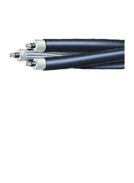
XLPE insulated non-m etallic screened aerial bundled cables to AS/NZS 3599.2 Aluminium conductors, aluminium alloy 1120 support conductor.
Physical Data
| Nominal conductor area mm2 |
Nominal conductor diameter mm | Average insulation thickness mm | Nominal diameter over insulation mm | Average insulation screen thickness mm | Nominal diameter over core mm | AAAC/1 1 20 support conductor | Nominal overall diameter mm | Approx mass kg/km | |
| Size no/mm | Diameter mm | ||||||||
| 6.35/11kV | |||||||||
| 35 | 6.9 | 3.4 | 14.9 | 1 | 17.1 | 7/4.75 | 14.3 | 48.4 | 1170 |
| 50 | 8.1 | 3.4 | 16 | 1 | 18.2 | 7/4.75 | 14.3 | 50.7 | 1320 |
| 70 | 9.6 | 3.4 | 17.6 | 1 | 19.8 | 7/4.75 | 14.3 | 53.9 | 1560 |
| 95 | 11.4 | 3.4 | 19.3 | 1 | 21.5 | 7/4.75 | 14.3 | 57.3 | 1860 |
| 120 | 12.8 | 3.4 | 20.7 | 1 | 22.9 | 19/3.50 | 17.5 | 63.3 | 2280 |
| 150 | 14.2 | 3.4 | 22.1 | 1 | 24.3 | 19/3.50 | 17.5 | 66.2 | 2570 |
| 185 | 15.7 | 3.4 | 23.6 | 1 | 25.8 | 19/3.50 | 17.5 | 69.2 | 2890 |
| 12.7/22kV | |||||||||
| 35 | 6.9 | 5.5 | 19.2 | 1 | 21.4 | 7/4.75 | 14.3 | 57.1 | 1540 |
| 50 | 8.1 | 5.5 | 20.3 | 1 | 22.5 | 7/4.75 | 14.3 | 59.3 | 1710 |
| 70 | 9.6 | 5.5 | 21.9 | 1 | 24.1 | 7/4.75 | 14.3 | 62.5 | 1990 |
| 95 | 11.4 | 5.5 | 23.6 | 1 | 25.8 | 7/4.75 | 14.3 | 66 | 2310 |
| 120 | 12.8 | 5.5 | 25 | 1 | 27.2 | 19/3.50 | 17.5 | 72 | 2760 |
| 150 | 14.2 | 5.5 | 26.4 | 1.1 | 28.8 | 19/3.50 | 17.5 | 75.2 | 3100 |
| 185 | 15.7 | 5.5 | 27.9 | 1.1 | 30.3 | 19/3.50 | 17.5 | 78.2 | 3460 |
Performance Data
| Nominal conductor area mm2 |
DC resistance at 20°C Ω/km | AC resistance at 50Hz 90°C Ω/km | Inductive reactance at 50Hz | Three-phase voltage drop at 50Hz 90°C mV/A.m | Conductor to screen capacitance µF/km | Continuous current rating, A | Earth fault current rating current rating conductor kA | Minimum bending radius (installed) mm | Projected diameter for wind loading mm | |||
| Still air | 1m/s wind | 2m/s wind | Core | Cable | ||||||||
| 6.35/11kV | ||||||||||||
| 35 | 0.868 | 1.11 | 0.153 | 1.94 | 0.202 | 110 | 155 | 185 | 3.3 | 260 | 480 | 41.3 |
| 50 | 0.641 | 0.822 | 0.145 | 1.45 | 0.224 | 130 | 185 | 225 | 4.7 | 270 | 510 | 43.5 |
| 70 | 0.443 | 0.568 | 0.134 | 1.01 | 0.254 | 160 | 235 | 285 | 6.6 | 300 | 540 | 46.7 |
| 95 | 0.32 | 0.411 | 0.127 | 0.745 | 0.286 | 195 | 285 | 345 | 9 | 320 | 570 | 50.2 |
| 120 | 0.253 | 0.325 | 0.127 | 0.604 | 0.312 | 225 | 335 | 410 | 11.4 | 340 | 630 | 54.6 |
| 150 | 0.206 | 0.265 | 0.122 | 0.506 | 0.338 | 255 | 380 | 465 | 14.2 | 360 | 660 | 57.4 |
| 185 | 0.164 | 0.211 | 0.118 | 0.419 | 0.366 | 295 | 435 | 530 | 17.5 | 390 | 690 | 60.4 |
| 12.7/22kV | ||||||||||||
| 35 | 0.868 | 1.11 | 0.161 | 1.94 | 0.144 | 110 | 155 | 185 | 3.3 | 320 | 570 | 49.9 |
| 50 | 0.641 | 0.822 | 0.153 | 1.45 | 0.158 | 130 | 185 | 220 | 4.7 | 340 | 590 | 52.2 |
| 70 | 0.443 | 0.568 | 0.142 | 1.01 | 0.177 | 160 | 230 | 275 | 6.6 | 360 | 630 | 55.4 |
| 95 | 0.32 | 0.411 | 0.134 | 0.749 | 0.197 | 195 | 285 | 340 | 9 | 390 | 660 | 58.8 |
| 120 | 0.253 | 0.325 | 0.134 | 0.609 | 0.214 | 225 | 330 | 395 | 11.4 | 410 | 720 | 63.2 |
| 150 | 0.206 | 0.265 | 0.129 | 0.511 | 0.23 | 255 | 375 | 450 | 14.2 | 430 | 750 | 66.4 |
| 185 | 0.164 | 0.211 | 0.125 | 0.424 | 0.247 | 290 | 430 | 520 | 17.5 | 460 | 780 | 69.4 |
AAAC/1120 Support Conductors
| Stranding & nom. wire dia no/mm | Nominal overall diameter mm | Cross-sectional area mm2 |
DC resistance at 20°C at 20°C | Minimum breaking load kN |
Recommended tension | Modulus ofelasticity Gpa | Coeff. of linear expansion 10 –6/°C | |
| Highest everyday kN | Max. working kN |
|||||||
| 7/4.75 | 14.3 | 124 | 0.239 | 27.1 | 4.1 | 13.6 | 59 | 23 |
| 19/3.50 | 17.5 | 182.8 | 0.163 | 41.7 | 6.3 | 20.9 | 56 | 23 |
ISO 9001:2015 JAS- ANZ

Power Systems
Tele Communication Systems
IEC Standard 61300-3-3--5
Quality Management
Quality Control